
Type 2 Surge Arrester
Home » Lightning Products » Power Supply Surge Protection » Type 2 Surge Arrester
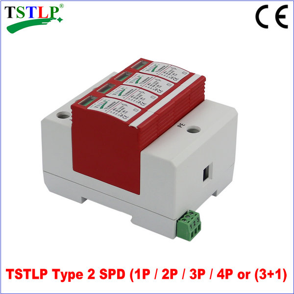
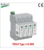
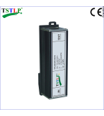
TS-385M20RM/4 Type 2 Surge Protection

Instruction
TS Series 3-PHASE Type 2 Surge Protection Device is designed according to IEC 61643-11 / GB 18802.11 for installation at LPZ 0B -1 or higher, protecting low voltage equipment from surge damages. Applied in pluggable Surge Protection Type 2 for various power supply system.
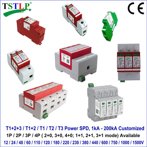
Similar & Related Surge Protective Device (SPD) for Electrical Panel Boxs
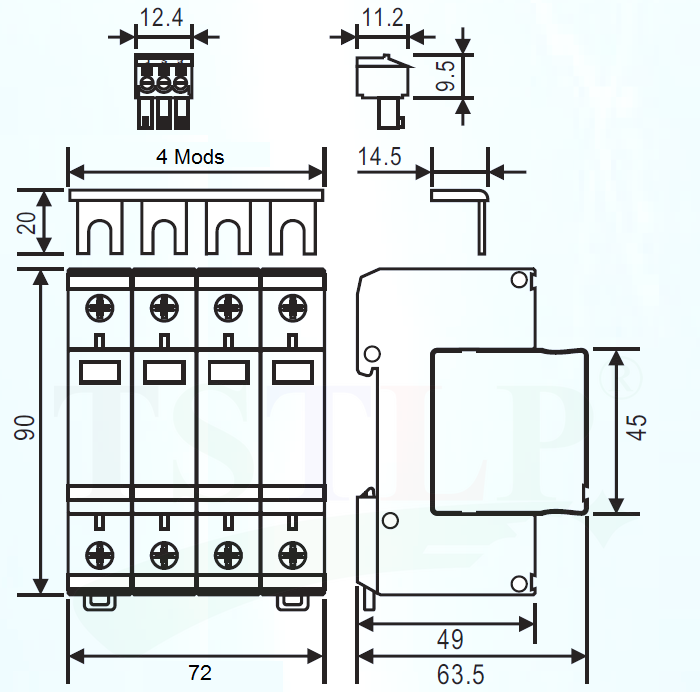
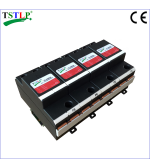
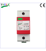
♦ Product Size of Class C Surge Arrester
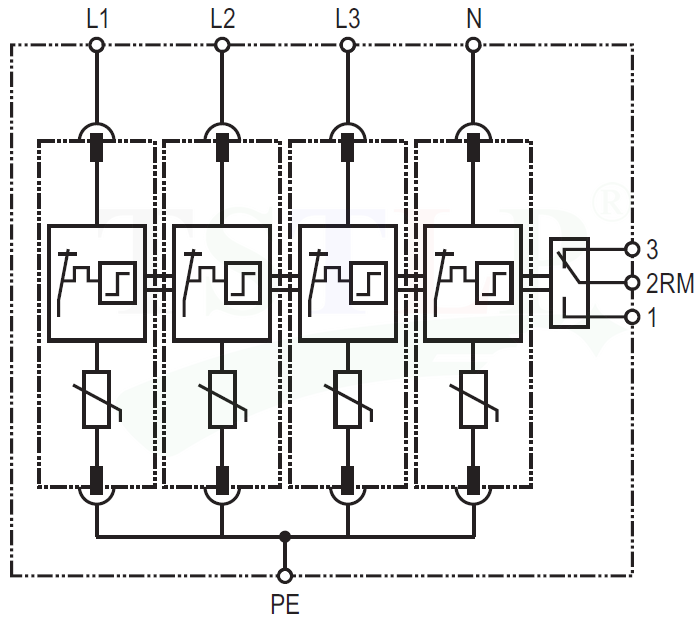
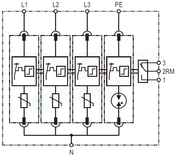
♦ Basic Circuit Diagram(4+0) of Type 2 / Class II Surge Protector
♦ Basic Circuit Diagram(3+1)
♦ Technical Data based on 385 VAC~ (110v / 180v / 220v / 230v / 380v / 440v also available)
|
Model Number 4+0 for TN-S system |
|
TS-385M30RM/4(S) ( 4+0 ) |
TS-385M20RM/4 ( 4+0 ) |
TS-385M10RM/4 ( 4+0 ) |
|
Rated voltage (max. continuous voltage) |
Uc |
385V~ |
385V~ |
385V~ |
|
Nominal discharge current (8/20) |
In |
30 KA |
20 KA |
10KA |
|
Max. discharge current (8/20) |
Imax |
60 KA |
40KA |
20KA |
|
Voltage protection level |
Up |
≤ 1.8 KV |
≤ 1.8 KV |
≤ 1.25 KV |
|
Voltage protection level 5kA |
Up |
≤ 1.35KV |
≤ 1.35KV |
≤ 1.0KV |
|
Response time |
tA |
≤ 25ns |
||
|
Max. back up fuse (L) |
|
200A gL/gG |
||
|
Max. back up fuse (L-L’) |
|
125A gL/gG |
||
|
Operating temperature range |
Tu |
-40°C...+80°C |
||
|
Relative humidity: |
|
≤95% (25°C) |
||
|
Cross-sectional area |
|
1.5mm2 ~ 25mm2 solid / 35mm2 flexible |
||
|
Mounting on |
|
35mm2 DIN rail |
||
|
Enclosure material |
|
Red thermoplastic, UL94-V0 |
||
|
Standards |
|
IEC 61643-11; GB 18802.11 |
||
|
Type of remote signalling contact |
|
Switching contact |
||
|
Switching capacity |
UN/IN |
AC:250V/0.5A DC:250V/0.1A,125V/0.2A,75V/0.5A |
||
|
Cross-sectional area for remote signalling contact |
|
Max. 1.5mm2 solid / flexible |
||
|
Certification |
|
CE (LVD, EMC) |
||
|
Model Number 3+1 for TN-S/TT system |
|
TS-385M30RM/4(S) ( 3+1 ) |
TS-385M20RM/4 ( 3+1 ) |
||||
|
Rated voltage (max. continuous voltage) |
Uc |
385V~ (L-N) |
255V~ (N-PE) |
385V~ (L-N) |
255V~ (N-PE) |
||
|
Nominal discharge current (8/20) |
In |
30 KA(L-N) |
40 KA(N-PE) |
20KA(L-N) |
40 KA(N-PE) |
||
|
Max. discharge current (8/20) |
Imax |
60 KA(L-N) |
65KA (N-PE) |
40KA(L-N) |
65KA (N-PE) |
||
|
Voltage protection level |
Up |
≤ 1.8KV |
≤ 1.5 KV |
≤ 1.8 KV |
≤ 1.5 KV |
||
|
Voltage protection level 5kA |
Up |
≤ 1.35KV |
|
≤ 1.35KV |
|
||
|
Response time |
tA |
≤ 25ns |
≤ 100ns |
≤ 25ns |
≤ 100ns |
||
|
Max. back up fuse (L) |
|
200A gL/gG |
|||||
|
Max. back up fuse (L-L’) |
|
125A gL/gG |
|||||
|
Operating temperature range |
Tu |
-40°C...+80°C |
|||||
|
Relative humidity: |
|
≤95% (25°C) |
|||||
|
Cross-sectional area |
|
1.5mm2 ~ 25mm2 solid / 35mm2 flexible |
|||||
|
Mounting on |
|
35mm2 DIN rail |
|||||
|
Enclosure material |
|
Red thermoplastic, UL94-V0 |
|||||
|
Standards |
|
IEC 61643-11; GB 18802.11 |
|||||
|
Type of remote signalling contact |
|
Switching contact |
|||||
|
Switching capacity |
UN/IN |
AC:250V/0.5A DC:250V/0.1A,125V/0.2A,75V/0.5A |
|||||
|
Cross-sectional area for remote signalling contact |
|
Max. 1.5mm2 solid / flexible |
|||||
|
Certification |
|
CE (LVD, EMC & RoHS) |
|||||
♦ Technical Data based on 275 VAC~
|
Model Number 4+0 for TN-S system |
|
TS-275M30RM/4(S) ( 4+0 ) |
TS-275M20RM/4 ( 4+0 ) |
TS-275M10RM/4 ( 4+0 ) |
|
Rated voltage (max. continuous voltage) |
Uc |
275V~ |
275V~ |
275V~ |
|
Nominal discharge current (8/20) |
In |
30 KA |
20 KA |
10KA |
|
Max. discharge current (8/20) |
Imax |
60 KA |
40KA |
20KA |
|
Voltage protection level |
Up |
≤ 1.5 KV |
≤ 1.8 KV |
≤ 1.25 KV |
|
Voltage protection level 5kA |
Up |
≤ 1.2 KV |
≤ 1.35 KV |
≤ 1.0 KV |
|
Response time |
tA |
≤ 25ns |
||
|
Max. back up fuse (L) |
|
200A gL/gG |
||
|
Max. back up fuse (L-L’) |
|
125A gL/gG |
||
|
Operating temperature range |
Tu |
-40°C...+80°C |
||
|
Relative humidity: |
|
≤95% (25°C) |
||
|
Cross-sectional area |
|
1.5mm2 ~ 25mm2 solid / 35mm2 flexible |
||
|
Mounting on |
|
35mm2 DIN rail |
||
|
Enclosure material |
|
Red thermoplastic, UL94-V0 |
||
|
Standards |
|
IEC 61643-11; GB 18802.11 |
||
|
Type of remote signalling contact |
|
Switching contact |
||
|
Switching capacity |
UN/IN |
AC:250V/0.5A DC:250V/0.1A,125V/0.2A,75V/0.5A |
||
|
Cross-sectional area for remote signalling contact |
|
Max. 1.5mm2 solid / flexible |
||
|
Certification |
|
CE (LVD, EMC & RoHS) |
||
|
Model Number 3+1 for TN-S/TT system |
|
TS-275M30RM/4(S) ( 3+1 ) |
TS-275M20RM/4 ( 3+1) |
|||
|
Rated voltage (max. continuous voltage) |
Uc |
275V~ (L-N) |
255V~ (N-PE) |
275V~ (L-N) |
255V~ (N-PE) |
|
|
Nominal discharge current (8/20) |
In |
30 KA(L-N) |
40 KA(N-PE) |
20KA(L-N) |
40 KA(N-PE) |
|
|
Max. discharge current (8/20) |
Imax |
60 KA(L-N) |
65KA (N-PE) |
40KA(L-N) |
65KA (N-PE) |
|
|
Voltage protection level |
Up |
≤1.5 KV |
≤1.5 KV |
≤1.25 KV |
≤1.5 KV |
|
|
Voltage protection level 5kA |
Up |
≤1.0KV |
|
≤1.0KV |
|
|
|
Response time |
tA |
≤ 25ns |
|
|
||
|
Max. back up fuse (L) |
|
200A gL/gG |
||||
|
Max. back up fuse (L-L’) |
|
125A gL/gG |
||||
|
Operating temperature range |
Tu |
-40°C...+80°C |
||||
|
Relative humidity: |
|
≤95% (25°C) |
||||
|
Cross-sectional area |
|
1.5mm2 ~ 25mm2 solid / 35mm2 flexible |
||||
|
Mounting on |
|
35mm2 DIN rail |
||||
|
Enclosure material |
|
Red thermoplastic, UL94-V0 |
||||
|
Standards |
|
IEC 61643-11; GB 18802.1; YD/T 1235.1 |
||||
|
Type of remote signalling contact |
|
Switching contact |
||||
|
Switching capacity |
UN/IN |
AC:250V/0.5A DC:250V/0.1A,125V/0.2A,75V/0.5A |
||||
|
Cross-sectional area for remote signalling contact |
|
Max. 1.5mm2 solid / flexible |
||||
|
Certification |
|
CE (LVD, EMC) |
||||
♦ MAIN CHARACTER
1, Standard single chip structure, pluggable
2, Consist of varistor and thermal disconnection device
3, High discharge capacity, quick response
4, Double thermal disconnection devices, provide more reliable protection
5, Multifunctional terminals for connection of conductors and busbars
6, Green windows will change to Red when fault occurs, and Remote Alarm Terminal Available
♦ INSTALLATION INSTRUCTION
According to lightning protection zones concept, for installation at LPZ 0B-1 or higher. This surge protection is usually installed in distribution-box or feeder bus of UPS,protecting devices or equipment downstream.Fuse must be installed at the upstream of the Surge Protection or the lightning arrester to make sure that protected system has double protection. The value of the fuse used in a Surge Protection system should be confirmed to:
1. The value of FUSE should not be larger than the max.withstand capacity of the Surge Protection's backup fuse value.
2. Under the status of the max. current in the power supply & close loop circuit available current, the fuse should be able to disconnect when overloaded or short-circuited.
3. Take 1 & 2 into consideration, the fuse should be as large as possible to allow the maximum surge discharge of Surge Protection.
♦ INSTALLATION STEPS
1) Check the product for integrity of the package; make sure the product WINDOW & LIGHT indicate green.
2) Mount the Surge Protection on the 35mm DIN rail.
3) Connect conductors, the cross-section area of cable must be larger than 6mm2 . The withstand voltage value of cable is not smaller than AC500V; ensure wiring reliable.
4) If need remote alarm, it should be connected signal lines to remote signal terminal 1 and 2, or 2 and 3 (When normal,1 and 2 open, 2 and 3 close; when fault, the state is reversed).
5) After above, switch on the power supply and turn on the circuit breaker,if the Surge Protection’s window does not appear red,(and if the Surge Protection with lights,3 green lights display HIGH GREEN and another red light doesn’t display HIGH RED), this indicates the unit is operating normally.
Regularly inspect the operating status, especially after lightning. Once the fuse upstream break, or the Surge Protection's window indicates red, electrician should check/replace the Surge Protection.
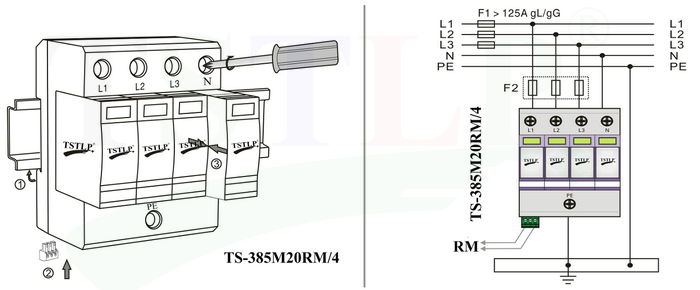
♦ Installation Diagram (4+0)
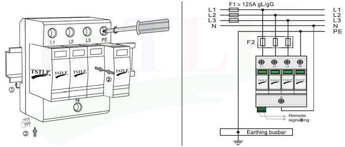
♦ Installation Diagram (3+1)
♦ WARNING:
1. The type 2 surge protector must be installed by electrically skilled person, conforming to national standards and safety regulations.
2. It is recommended that installation should be done under power off condition.
- CONTACT US
 0086 13926098193
 0086 20 28819702 EXT 27806
 [email protected]
 Hongdiyuan Industrial Park, Wufeng Avenue, Linjiang Town, Jiangdong New District, Heyuan, Guangdong,P.R.C.
 http://www.tslpro.com
 +86 13926098193
 F13926098193
 tslpro.tstlp
-


