
Network Surge Arrester
Home » Lightning Products » IT Surge Protection » Network Surge Arrester
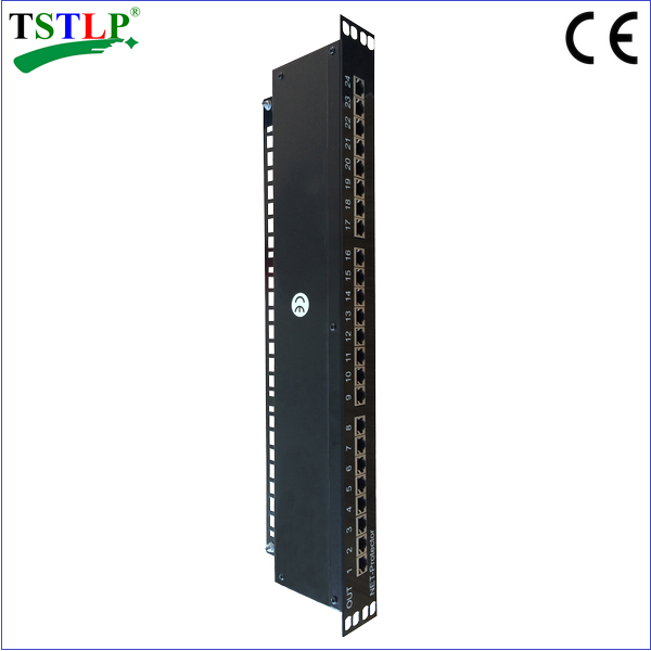
TS-24RJ45/5/8(1000M) Ethernet Surge Suppression

Previous : TS-8RJ45/5/8(1000M) Ethernet Surge Protection
Next : TS-POE5 POE Surge Arrester
Instruction
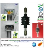
♦ TS series RJ45 port Ethernet Surge Suppression is designed to protect network equipment from interruption caused by surge current;
Ethernet Surge Suppression with 16/24 Ports RJ45 interface, all protected by four pairs lines protected. Designed according to IEC 61643-21; GB 18802.21; YD/T 1542.Mainly used for offices and industry like Gigabit Ethernet, ATM or ISDN system,like VOIP can be protected.(e.g. Telecom-munication server, router,computer, and so on). Module design for standard 19"distribution cabinet.
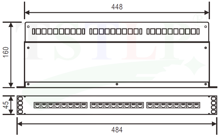
♦ Product Size
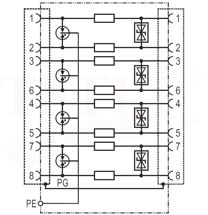
♦ Basic Circuit Diagram
♦ Technical Data
|
Model |
|
TS-24RJ45/5/8(1000) |
|
Nominal voltage |
Un |
5V- |
|
Rated voltage (max. continuous voltage) |
Uc |
6V- 4.2V~ |
|
Normal current |
IN |
0.35A |
|
Nominal discharge current (8/20) |
In |
300A (line-line) 2.5KA (line-PG) |
|
Max. discharge current (8/20) |
Itotal |
5KA (line-PG) |
|
Voltage protection level at In |
Up |
≤15V (line-line) ≤150V (line-PG) |
|
Voltage protection level at 1kV/ms |
Up |
≤ 13V (line-line) ≤ 150V (line-PG) |
|
Capacitance |
C |
≤ 35pF (line-line) ≤35pF (line-PG) |
|
Response time |
tA |
≤10ns (line-line) ≤10ns (line-PG) |
|
Max. data transmission rates |
Vs |
1000 Mbits/s |
|
Dimension(mm) |
|
L*W*H 24P:448*160*45mm |
|
Operating temperature range |
|
-40°C...+80°C |
|
Relative humidity |
|
≤95% (25°C) |
|
Connection (input / output) |
|
RJ45 shield socket |
|
Pining |
|
1/2, 3/6, 4/5, 7/8 |
|
Shield earthing |
|
Metal enclosure |
|
Standards |
|
IEC 61643-21; GB 18802.21; YD/T 1542 |
|
Certification |
|
CE(LVD,EMC) |
♦ MAIN CHARACTER
1, Low voltage protection level & Low insertion loss
2, Quick response, high transmission speed
3, Available with 16/24 ports RJ45 connection.
|
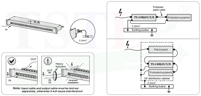
INSTALLATION INSTRUCTION 1. This Ethernet Surge Suppression is connected in series to the protected device. 2. Can be mounted in the 19" distribution cabinet.. 3. The out terminal should be connected to the protected devices. 4. SPD's earthing terminal must be connected to nearby earthing BusBar or the metal earthing enclosure of protected device. 5. After above, you should ensure the circuit is functioning. Regularly inspect the operating status, especially after lightning. Once the communication is off, electrician should check/replace the SPD. |
|
INSTALLATION DIAGRAM
|
|
WARNING: 1, The device must be installed by electrically skilled person, conforming to national standards and safety regulations. 2, It is recommended that installation should be done under power off condition. |

- CONTACT US
 0086 13926098193
 0086 20 28819702 EXT 27806
 [email protected]
 Hongdiyuan Industrial Park, Wufeng Avenue, Linjiang Town, Jiangdong New District, Heyuan, Guangdong,P.R.C.
 http://www.tslpro.com
 +86 13926098193
 F13926098193
 tslpro.tstlp
-


